4.2. Geometry
The Geometry pane is used to define the model geometry. This includes whether the model is 2D or 3D, and the overall domain extents (xmin, xmax, ymin, ymax, zmin, zmax). If there is complex geometry, the “Auto-size” button can automatically set the extents to surround the geometry.
The geometry section provides tools for adding geometry objects (from STL files, or primitive elements), filters to transform geometry objects, and wizards to automate creating common complex geometries. Geometry objects can be copied, removed, or combined using Boolean operations. All the geometry operations are done using the Visualization Toolkit (VTK)’s library.
Geometry toolbar icons:
Icon |
Description |
|---|---|
|
Add geometry to model |
|
Modify selected geometry with filter |
|
Add geometry from wizard |
|
Remove the selected geometry |
|
Add duplicate of the selected geometry (copy/paste) |
|
Add union of two or more selected geometries |
|
Add intersection of two or more selected geometries |
|
Add difference of two or more selected geometries |
In the geometry tree, the geometry object is displayed with the following icons:
Icon |
Geometry Type |
|---|---|
|
polydata |
|
implicit |
|
filter |
|
union |
|
intersect |
|
difference |
4.2.1. Adding Geometry
To add a Geometry object, click on the ![]() (add) icon and select
the geometry to add from the drop-down menu.
(add) icon and select
the geometry to add from the drop-down menu.
There are two types of geometric objects supported in the GUI: implicit functions (quadrics), and objects defined by polydata (everything else: STL files, procedural shapes, primitives, parametrics, wizard geometry).
The following geometric objects can be added:
STL files (select a *.stl file from a file dialog)
Procedural shapes (cylinder, bend, circle to rectangle, body of revolution)
Implicit (Quadric) functions (sphere, box, cylinder, cone, quadric, superquadric)
Primitives (sphere, box, cylinder, cone)
Parametrics (torus, boy, conic spiral, etc.)
4.2.2. Procedural shapes
Procedural shapes were introduced in the 21.1 release. These are triangulated polydata objects that are defined by a series of parameters. They offer better control on the triangles quality than implicits or primitives.
4.2.2.1. Cylinder
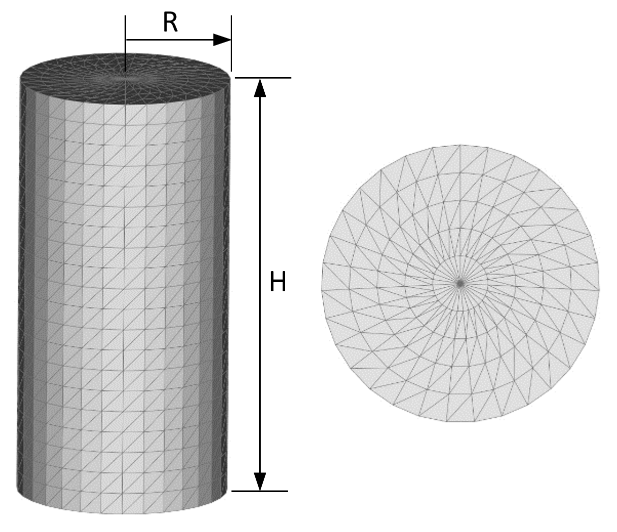
- Parameters:
Radius (R)
Height (H)
Number of divisions along the height
Starting angle in the circumferential direction
Ending angle in the circumferential direction
Number of divisions along the circumferential direction
Bottom cap
Number of divisions in the bottom cap’s radial direction
Top cap
Number of divisions in the top cap’s radial direction
The top and bottom caps are shaped like fans, i.e., they converge radially towards the center of the cap. Caps are not needed if the cylinder extends past the MFiX domain in the axial direction, when inlet/outlet boundary conditions are defined along the MFiX box (say at y=ymin and y=ymax for a vertical cylinder).
It is recommended to include caps when combining shapes (union, intersection, difference) since the boolean operations are more robust with closed shapes.
4.2.2.2. Bend
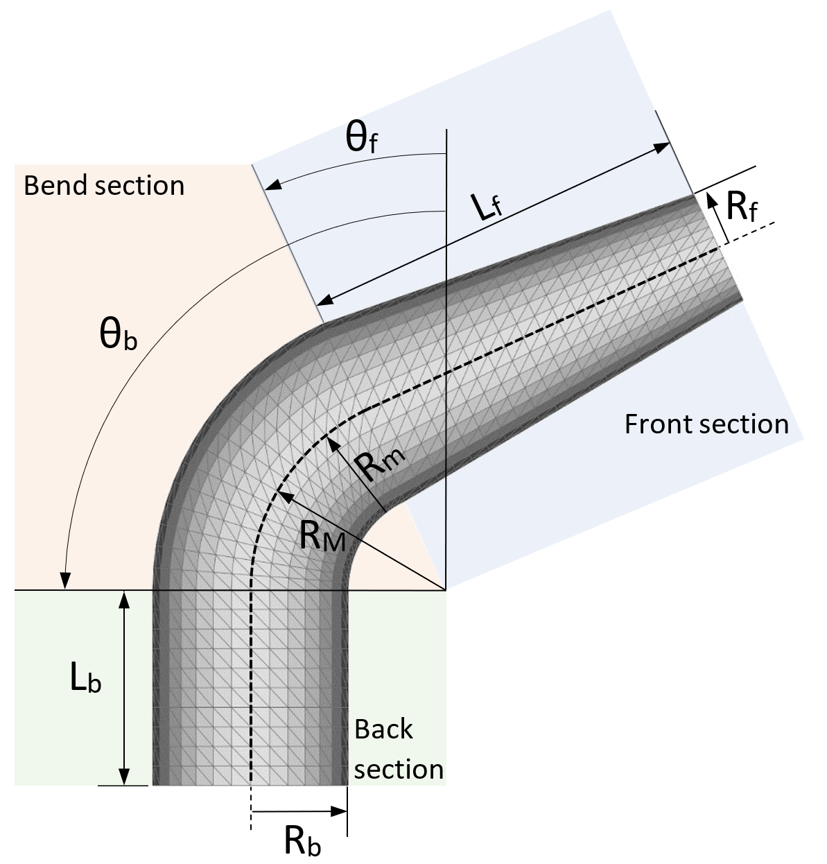
- Front section:
Length (L f)
Radius (R f)
Number of divisions along the front section length
- Back section:
Length (L b)
Radius (R b)
Number of divisions along the back section length
- Bend section:
Major radius (R M)
Minor radius (R m)
Starting angle (\({\theta}\) f)
Ending angle (\({\theta}\) b)
Number of divisions in the angular direction
- Circumference:
Starting angle in the circumferential direction
Ending angle in the circumferential direction
Number of divisions along the circumferential direction
- Caps:
Bottom cap
Number of divisions in the bottom cap’s radial direction
Top cap
Number of divisions in the top cap’s radial direction
4.2.2.3. Cylinder to rectangle
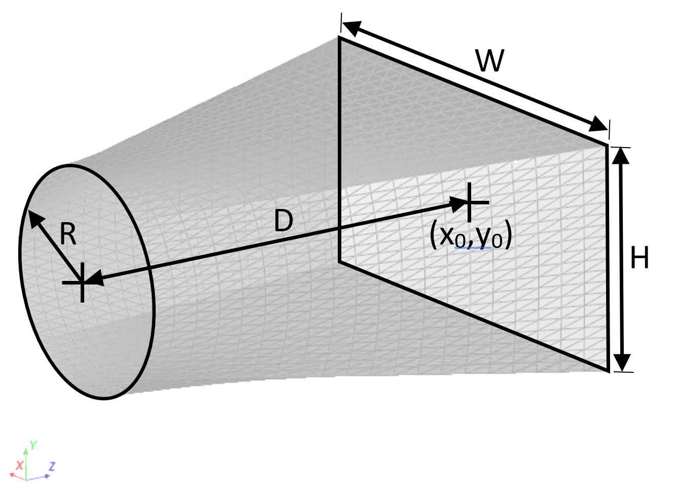
Distance: distance between circle and rectangle in z-direction (D)
Resolution: number of divisions in the z-direction
- Circle section:
Radius (R)
Cap: option to fill the circle
Resolution: Number of divisions along the cap radial direction
- Rectangle section:
Width in x-direction (W)
Resolution: number of divisions along the rectangle’s width
Height in y-direction (H)
Resolution: number of divisions along the rectangle’s height
X Offset, Y Offset: location of the rectangle’s center (x0,y0)
Cap: option to fill the rectangle
Notes:
The cylinder’s center is located at (x=0,y=0,z=0).
The number of divisions along the circle’s circumference is the sum of the number of divisions of the rectangle’s width and height.
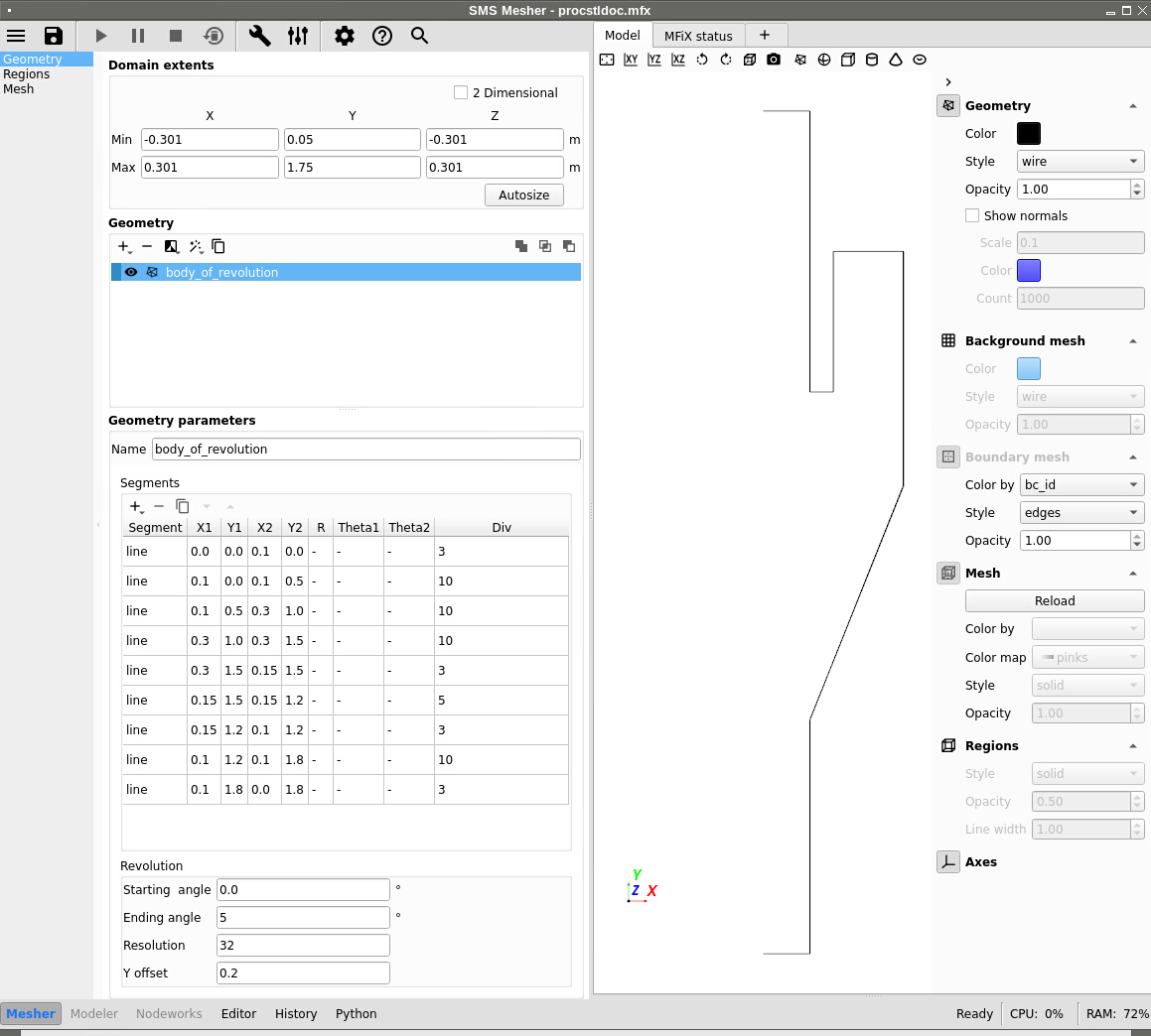
4.2.2.4. Body of revolution
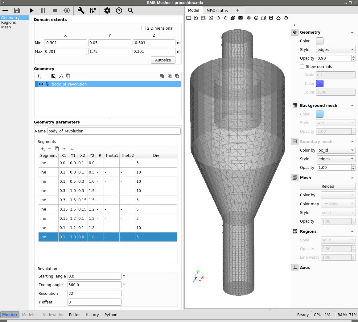
The body of revolution shape revolves a profile (xy plane) around the z-axis.
A series of line or arc segments is defined in a table. Click the ![]() (plus sign) to add a segment and select either line or arc.
(plus sign) to add a segment and select either line or arc.
Segments:
- Line:
(X1, Y1): coordinates of the first point
(X2, Y2): coordinates of the second point
Div: Number of divisions along the segment
- Arc
(X1, Y1): coordinates of the arc’s center
R: radius
Theta1: starting angle (degrees)
Theta2: ending angle (degrees)
Div: Number of divisions along the segment
Revolution:
Starting angle (degrees)
Ending angle (degrees)
Resolution: Number of divisions along the circumferential direction
Offset: offset in y-direction (per revolution)
Notes:
See figure above for an example. The first and last segments are used to close the shape (bottom and top caps). Having a closed volume is preferred if the shape is used in boolean operation with another shape.
For complex shapes, it may be useful to align the view in the xy plane, set the ending angle to a small value (say 5 degrees) and set the style to wire with a black color. This allows to get a better view of the profile (see figure below). Once the profile is properly defined, set the ending angle to 360 degrees to generate the full 3D shape.
4.2.3. Applying Filters
To apply a filter to the selected geometry, select a filter from the Filter menu. The filter options can be edited in the parameter section. The following filters are included:
Filter |
Description |
vtk class |
|---|---|---|
sample implicit |
converts an implicit function to polydata |
vtkSampleFunction |
transform |
rotate, scale, translate polydata |
vtkTransformPolyDataFilter |
clean |
merge duplicate points and remove unused points and degenerate cells |
vtkCleanPolyData |
fill holes |
fill holes |
vtkFillHolesFilter |
triangle |
make sure all polys are triangles |
vtkTriangleFilter |
decimate |
reduce the number of triangles |
vtkDecimatePro |
quadric decimation |
reduce the number of triangles |
vtkQuadricDecimation |
quadric clustering |
reduce the number of triangles |
vtkQuadricClustering |
linear subdivision |
subdivide based on a linear scheme |
vtkLinearSubdivisionFilter |
loop subdivision |
subdivide based on the Loop scheme |
vtkLoopSubdivisionFilter |
butterfly subdivision |
subdivide based on 8-point butterfly scheme |
vtkButterflySubdivisionFilter |
smooth |
move points based on Laplacian smoothing |
vtkSmoothPolyDataFilter |
windowed sinc |
move points based on a windowed sinc function interpolation kernel |
vtkWindowedSincPolyDataFilter |
reverse sense |
reverse order and/or normals of triangles |
vtkReverseSense |
Refer to the VTK website for details.
4.2.4. Wizards
Three wizards are available to more easily create common multiphase flow geometries: cyclones, reactors, and hoppers. A special “distributed” wizard is used to distribute one geometry inside another geometry with random, cubic, or body centered cubic positions. Random rotations can also be applied with the wizard.


4.2.5. Remove & Copy
To remove a selected geometry, click the ![]() (Remove) button. If a
geometry is grouped as part of a Boolean Operation, removing it is
disabled until that Boolean Operation is removed first.
(Remove) button. If a
geometry is grouped as part of a Boolean Operation, removing it is
disabled until that Boolean Operation is removed first.
To duplicate the selected geometry, click the ![]() (Duplicate) button. If
multiple geometry objects are selected, duplication is disabled.
(Duplicate) button. If
multiple geometry objects are selected, duplication is disabled.
4.2.6. Boolean Operation
There are two types of geometric objects supported in the GUI: implicit
functions (quadrics) and objects defined by polydata (everything else: STL
files, primitives, parametrics, wizard geometry). Boolean operations cannot be
performed between polydata and implicit geometry objects; the implicit function
needs to be converted to polydata by using the sample implicit filter.
Converting the implicit function also needs to be done in order for the GUI to
export a STL file that the mfixsolver can use.
Boolean operations can only be performed with geometry objects of the same type (implicit, polydata). Boolean operations can not be performed between polydata and implicit geometry objects. If an implicit and a polydata must be managed together, the implicit object must be first converted to a polydata object using the sample implicit filter.
Note
Boolean operation between two polydata objects is supported by MFiX, but for complex objects the VTK library may crash.