4.8. Initial Conditions
Initial Conditions (ICs) are specified in the Initial conditions task pane. ICs summarized in the IC summary table illustrated in Fig. 4.5. The MFiX solver will apply ICs in the order that they are defined in this pane. As a result, if two or more regions overlap, the IC with the larger index (ID) is used in the intersecting region. IC IDs are shown in the table, and can be changed using the up and down arrows.
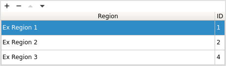
Fig. 4.5 Initial condition (IC) summary table.
4.8.1. Creating an Initial Condition Region
To define an initial condition, there must be a region already defined in the Regions Pane.
Initial conditions are specified over rectangular regions corresponding
to the scalar grid. A new IC region is created by clicking the add
button,  , at the top of the IC region table, and selecting one or
more valid regions (see Fig. 4.6).
, at the top of the IC region table, and selecting one or
more valid regions (see Fig. 4.6).
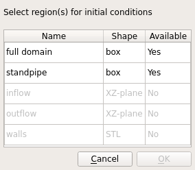
Fig. 4.6 Initial condition region selection popup window.
Valid IC Regions
Box regions
XY-planes (2D simulations only)
Invalid IC Regions
Any region already used by another IC
XZ- and YZ-planes
Point regions
STL regions
4.8.2. Setting Fluid Phase Initial Values
When the fluid phase is enabled, initial values for fluid field variables must be specified for the entire computational domain. The models being solved dictate which variables require an initial value.
Volume Fraction The fluid phase volume fraction has a default value of one. If solids are defined and given volume fractions greater than zero, the fluid phase volume fraction is automatically calculated by subtracting the sum of the solids phase volume fractions from one.
Temperature The fluid phase temperature has a default value of 293.15K. Specification of the fluid temperature is required when the following settings are used:
The energy equation is solved
Fluid density is computed by the Ideal Gas Law
Fluid viscosity is computed by the Sutherland’s Law
Pressure An initial pressure field may be specified. If none is provided, the fluid solver will attempt to impose a hydrostatic pressure drop across the domain.
Velocity The fluid phase velocity field has a default value of zero.
Species Mass Fractions Species mass fractions must be defined for all species when solving the species transport equations. By default the species mass fraction of the last defined fluid species is set to one and all others are set to zero. The total of all species mass fractions must equal one.
Turbulence If using the mixing length turbulence model, a mixing length scale must be defined for the whole domain.
If solving the k-ε turbulence model, initial values for turbulent kinetic energy and turbulent dissipation must be provided.
Radiation Coefficient A radiation coefficient has a default value of zero, and can only be specified when solving the energy equations. The default value is strongly recommended.
Radiation Temperature The radiation temperature has a default value of 293.15K, and can only be specified when solving the energy equations. The default value is strongly recommended.
4.8.3. Setting Solids Phase Initial Values
When one or more solids phases are enabled, initial values for solids field variables must be specified for the entire computational domain. The models being solved dictate which variables require an initial value.
Volume Fraction The solids phase volume fraction has a default value of zero. The sum of all solids phase volume fractions are used to calculate the volume (void) fraction of the fluid phase. If solids are defined and given volume fractions greater than zero, the fluid phase volume fraction is automatically calculated by subtracting the sum of the solids volume fractions from one.
Inventory (DEM solids only) Amount of solids (by mass) in the initial condition region.
Particle count (DEM solids only) Number of particles in the initial condition region.
Particle size distribution (DEM solids only) Particle size distribution in the initial condition region. This can be left as “Uniform” (default) and the particle diameter (d_p0) defined in the Solids>Material pane will be used. If a PSD was defined in the Solids>DEM pane, it can be chosen here to initialize particles in this region with a PSD.
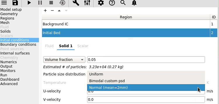
Fig. 4.7 PSD used in initial condition region.
Temperature The solids phase temperature has a default value of 293.15K. Specification of solids temperature is required when solving energy equations.
Pressure (TFM solids only) Solids pressure is an optional input for TFM solids models. There is only one value for all solids phases.
Granular Temperature The initial granular temperature has a default value of zero.
For TFM solids, granular temperature can only be specified when solving one of the non-algebraic viscous stress models.
For DEM solids models, a value may be specified when using the automatic particle generator to modify the initial particle velocity distribution.
Species Mass Fractions Species mass fractions must be defined for all species when solving the species transport equations. By default the species mass fraction of the last defined fluid species is set to one and all others are set to zero. The total of all species mass fractions must equal one.
Fit particles to region (DEM solids only) This option is used with the automatic particle generator to expand the initial particle lattice to span the region.
DEM seeding options
Initial lattice distribution (DEM solids only) Particles are initially seeding on a lattice, which can be cubic or hexagonal arrangement. Hexagonal arrangement can typically achieve higher packing density than cubic arrangement.
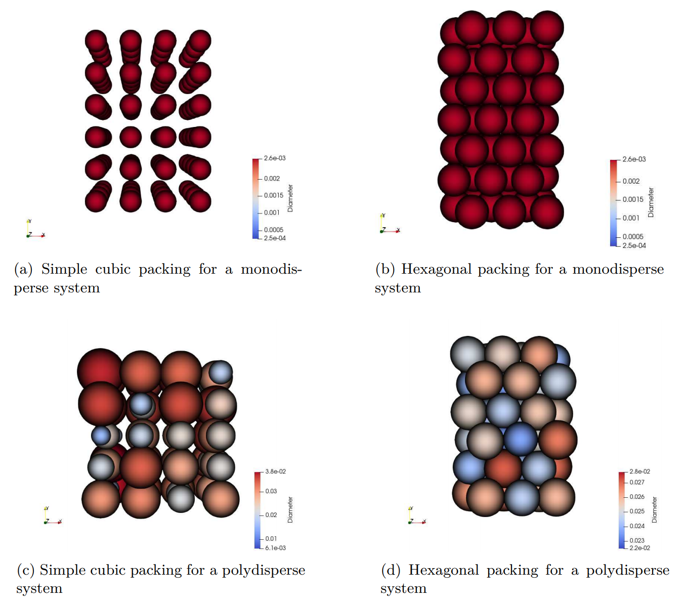
Fig. 4.8 Examples of cubic and hexagonal lattice
Spacing between particle (DEM solids only) Spacing (expressed as a fraction of the largest diameter, must be between zero and 1) between particles in the lattice. Default value is 0.05 (5% of the particle diameter). This spacing applies equally in all directions unless one of the spacing factors (x,y, or z direction) is less than one.
Spacing factor in x-direction (DEM solids only) Factor used to reduce the spacing in the x-direction (between zero and one). This factor is a multiplier to the overall spacing (if the spacing is 0.05 and the factor in x-direction is 0.5, then the effective spacing in the x-direction is 0.025 times the diameter).
Spacing factor in y-direction (DEM solids only) Factor used to reduce the spacing in the y-direction (between zero and one). This factor is a multiplier to the overall spacing (if the spacing is 0.05 and the factor in y-direction is 0.5, then the effective spacing in the x-direction is 0.025 times the diameter).
Spacing factor in z-direction (DEM solids only) Factor used to reduce the spacing in the z-direction (between zero and one). This factor is a multiplier to the overall spacing (if the spacing is 0.05 and the factor in z-direction is 0.5, then the effective spacing in the x-direction is 0.025 times the diameter).
Random factor applied to particle positions (DEM solids only) Factor to randomize the particle position around the baseline lattice position (between zero and one). The same factor applies in all directions unless a random factor less than one is specified in the x,y or z-direction.
Random factor in x-direction (DEM solids only) Factor used to reduce the randomness in the x-direction (between zero and one).
Random factor in y-direction (DEM solids only) Factor used to reduce the randomness in the y-direction (between zero and one).
Random factor in z-direction (DEM solids only) Factor used to reduce the randomness in the z-direction (between zero and one).
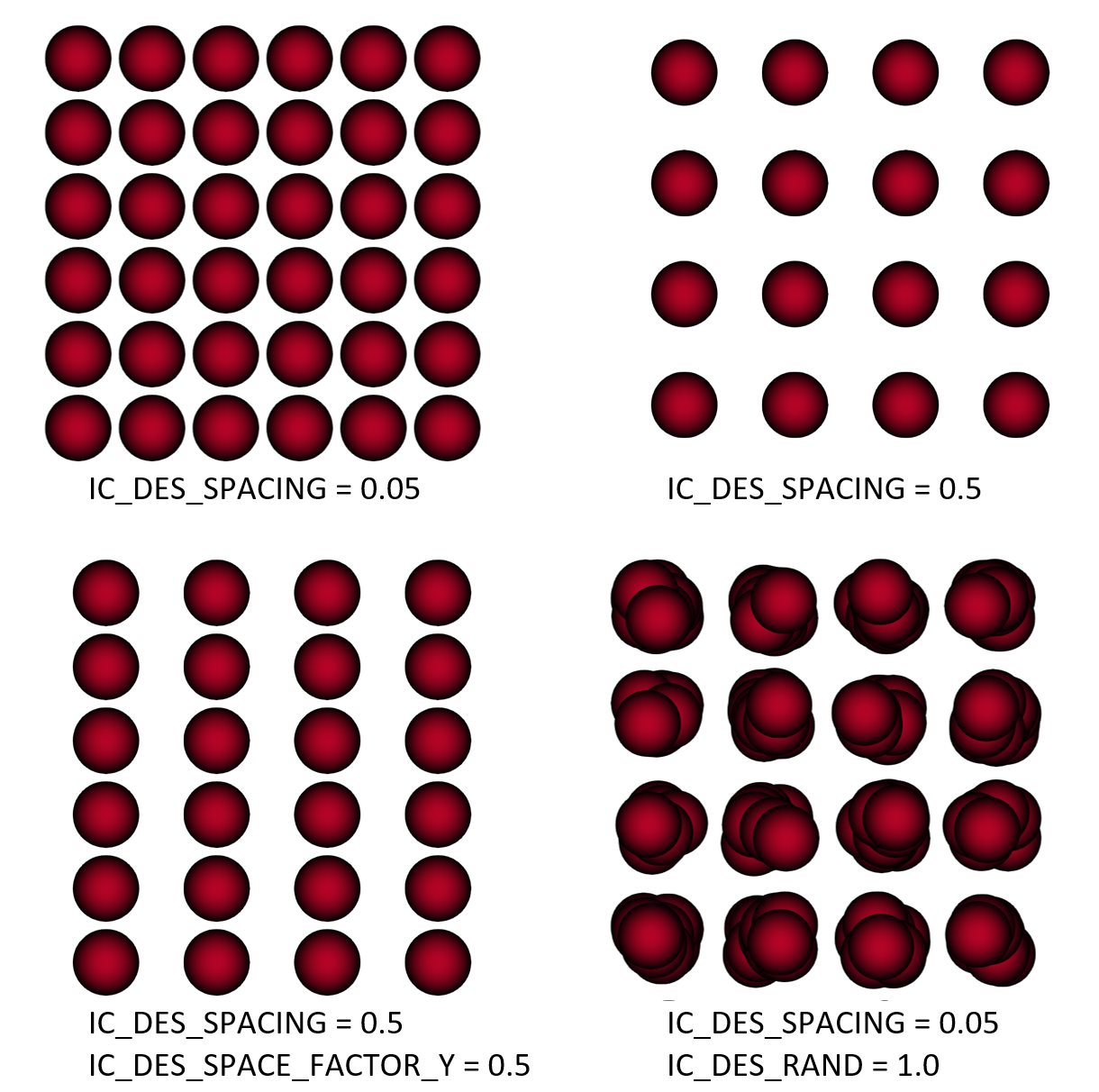
Fig. 4.9 Examples of spacing options with cubic lattice
Radiation Coefficient The radiation coefficient has a default value of zero, and can only be specified when solving the energy equations. The default value is strongly recommended.
Radiation Temperature The radiation temperature has a default value of 293.15K, and can only be specified when solving the energy equations. The default value is strongly recommended.
4.8.4. Setting User-Defined Scalar Initial Values
When one or more user-defined scalars are enabled, initial values for the scalars must be specified for the entire computational domain.
Scalar Value For each user-defined scalar, an initial field value must be provided. By default, all scalars are set to zero.