I am getting the following error
IC_K_B > IC_K_T
I presume my “bottom” initial condition index in the K direction is higher than my “top” index.
I am not familiar with the ascii input file *.mfx but I have been working in the GUI and I am not seeing how I am introducing this error. I am using an stl file created in solidworks for my geometry. Any suggestions how to find out what is causing this error?
Is your IC region a volume (it should not be a plane in 3D)? Check the z-extent and make sure it is larger than a grid cell.
Also check that you haven’t swapped the “From” and “To” fields in the GUI when defining the region. This is very easy to do and the 18.1 release doesn’t check if you defined them backwards.
I have two regions defined for initial conditions and I am getting the error on both. The first region is the Background IC which is automatically created over the entire min and max of each direction. The second I created myself. Both of these regions have the From and To as zmin and zmax, so something funny is happening.
If you want, you can post your case files and we can take a look.
I would appreciate you looking at it. But it says that I am a new user and cannot upload. I will contact the forum person.
Here are the files. Thanks for your help.base.mfx (18.1 KB)
feed fuidizer with mods and no plenum_v2.stl (319.5 KB)
I would appreciate it if someone could look at my case files.
The error message you see comes from the z control point #3 that is associated with a 1-cell segment and a stretch ratio of 20. Change it to one (for a 1-cell segment, the only valid stretch ratio is 1).
This being said, there are other issues:
- The mesh is still too coarse to resolve the tiny tube thickness, and will need to be refined further
- You are modeling an external flow right now. Go to the Mesh>Mesher pane and uncheck “External Flow”
- The STL file has a lot of very long and narrow triangles that will make the meshing difficult. I suggest you split these triangles so they have a smaller aspect ratio
Thank you for the help. What do you recommend for the minimum number of cells through a wall thickness?
Bare minimum is 2 to 3 cells
I looked at out_stl_value in the mfx file and with the external flow box checked it is set to 1.0 which according to the manual 5.3.19, the domain outside of the STL geometry is excluded from computation, i.e., an internal flow is computed. So if external flow is checked it sounds like external is excluded. Am I correct? It is dependent on the facet normals which for my stl is pointing outward.
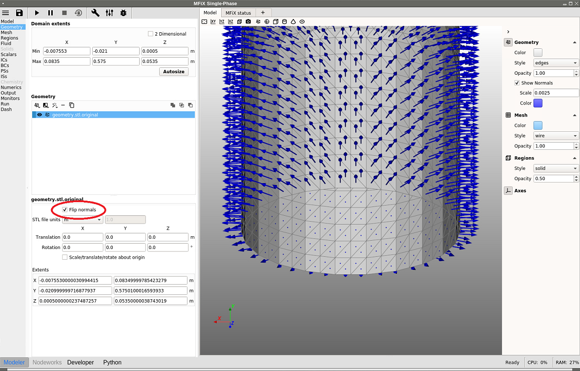
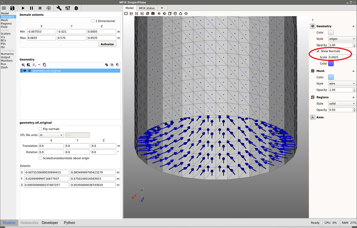
So the stl standard is for normals to point out of the solid. MFiX is backwards and expects the normals to point inside the domain. That’s why this option can get confusing. At the end of the day, make sure your cells are what you expect. If not, flip the out_stl_value sign.
In CFD, the domain we model is the fluid region, not the solid region. The normals must point towards the fluid region (i.e. out of the solid). For internal flows where there are inlets and outlets, the stl file will be an open shell describing the interface (wall) between solid and fluid regions.
Note that the upcoming 19.1 release will have a option to display the stl normal vectors and flip them if needed, to make it easier to spot and fix this common error.
This is all very helpful. Thank you. Concerning enough resolution through walls or grid resolution in general where high resolution in one direction can result in high cell aspect ratios, what is the maximum aspect ratio for the structured grid cells that one would not want to exceed in mfix?