I’m a beginner on MFIX.
I’m trying to simulate a very simple case, which is a duct flow with particles inside.
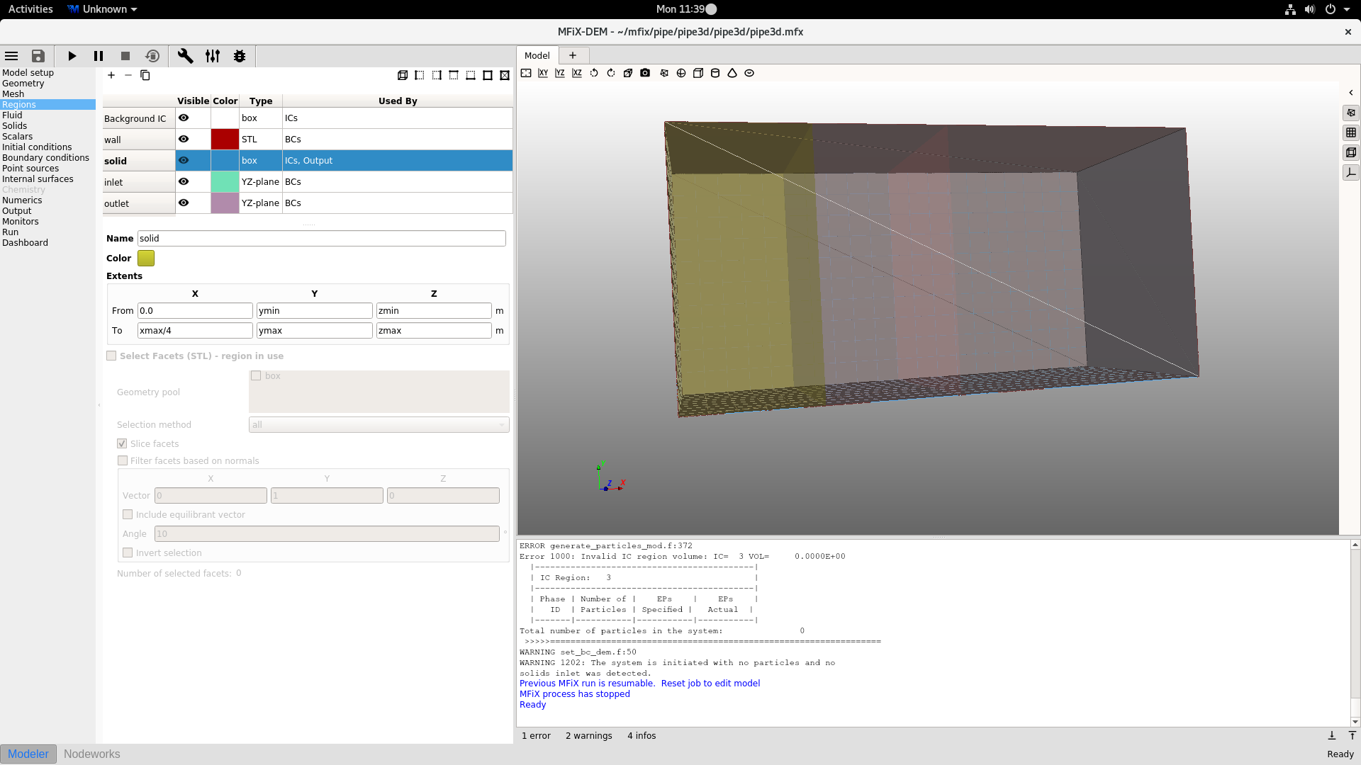
I run the case and always get the error message “Invalid IC region volume”.
I tried to solve this by changing the case settings, but always get the same error.
I don’t know what is wrong.
Please help!
You don’t need an STL file to define a simple box geometry. By default, MFIX will impose no-slip walls on the edges of the domain that are not specified. This case will run if you remove the STL boundary condition.
I met the same problem as the poster. I run the attached mfix file, and remove the bounary condition “wall” defined by the poster. But there is still something wrong. It prompts that " NO CARTESIAN GRID BOUNDARY CONDITION SPECIFIED.
AT LEAST ONE BC_TYPE MUST START WITH CG (FOR EXAMPLE CG_NSW)
RUN ABORTED "
What does it mean? and how should i do to resolve it ?
Thank you for your reply! It ran successfully after deleting the box on the geometry pane. But i am still confused that it seems the STL file cause the problem, as you explained above, rather than the boundary condition. Why does it happen?
It does not seem to be a problem to add such a simple STL file. Whether there are other methods to run this case successfluly, if the STL file is not removed?
Could you give us some suggestions on setting the geometry to avoid this kind of problem?
The original issue your had (Invalid IC having zero volume) comes from the STL normals pointing in the wrong direction. This leads to modeling the flow outside of the STL geometry (external instead of internal flow), which is itself outside of the MFiX domain extent, resulting in an unusable mesh (zero cell).
You could flip the normals and get a computational mesh, but you would still get the following issues:
The corners may not be well defined because when using cut-cells, we assume only one cut face per cell, which tends to round off sharp corners.
The wall BC applies to the entire STL geometry. This overlaps with inlet and outlet BCs and creates a conflict (two BCs defined at the same boundary). To overcome that, you would need to split the STL file into the wall facets and the inlet and outlet facets (or only keep the wall facets).
For the above reasons, it is not worth using an STL file when the geometry is rectangular. Deleting the wall BC was not sufficient, because when MFiX reads the STL file, it will attempt to match the STL facets to defined BCs, and will quit if no match is found.
We are trying to improve the meshing workflow so this kind of confusion can be avoided.
Thank you for your detailed interpretation. For my own case, a simple case as the poster’s, it ran sucessfully without the STL file, as you suggested. Based on your further interpretation, i remained the STL file and set the region “walls” without “inlet” and “outlet” facets, however, the same error took place again. And i guess that the error is not caused by " cut-cells ". As shown below, for such a simple rectangular box, cut-cell technique may not be reqiured. Is it right? Honestly, i don’t know cut-cells technique well. I post the mfix file of my case. If it is convenient for you, could you check it and give me some advice?