I am getting singular matrix detected when solving for U_g and U_s so it looks like the x momentum. What could be causing this or where should I look to correct this?
Please provide more information. If you can, post the mfx file.
Here are the input files. The stl can be downloaded with the link stl file.zip - Google Drive base.mfx (18.2 KB)
Can anybody look at my case?
Thank you for your patience. I don’t have a solution yet, but this is probably due to a bad mesh. Others may provide additional guidance.
A few points:
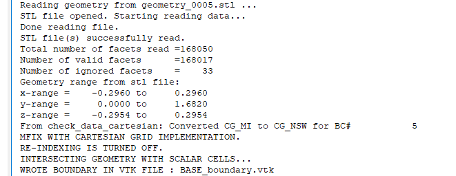
- The STL file looks better, but look at the output:
STL file(s) successfully read.
Total number of facets read =134588
Number of valid facets =104889
Number of ignored facets = 29699
This is an indication small triangles are still present. You may get better results by reducing the facet angle tolerance and decreasing the intersection tolerance.
-
You are still modeling the outside of the geometry. Make sure you look at the mesh by saving a vtk file. Uncheck the “External Flow” box in Mesh> Mesher
-
Your domain box cuts the stl on the side. Increase the x and z range to ±0.296 m
-
Some of the mesh tolerance will need to be adjusted due to the highly stretched nature of the mesh.
Thank you for the points. I am no longer getting singular matrix errors but still getting “Run divered/stalled” decreasing time steps. I am wondering if large cell aspect ratios are contributing. How large is acceptable?
An aspect ratio or 10 or 20 may be acceptable. Other factors that may lead to small time steps are
- Large, sudden changes in grid spacing. Try to gradually increase/decrease grid spacing
- Small cells (in volume). Due to the mesh refinement, some (uncut, rectangular) cells have a very small volume
- Multiple solids phases
- Bad initial of boundary conditions
Here is an image of the BASE_boundary.vtk file created by MFIX at startup. There are boundary faces that seem to be missing. Should this be a clue for me that my stl file is causing difficulty to the mesher?
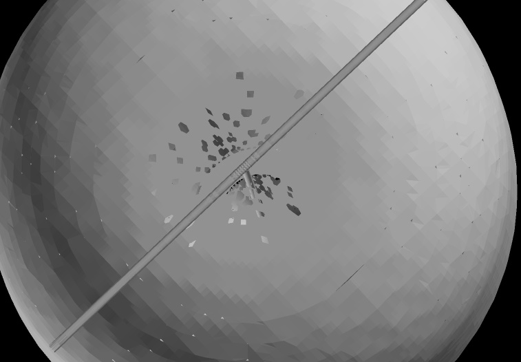
@jeff.dietiker correct me if I am wrong, but the boundary.vtk is just the cut cell faces? So if there are holes in that file, those faces might just align with a normal uncut cell?
What is your current ignored facets? Need to get that much lower.
Might be able to use some of the filters in the GUI to help clean up the facets. I’ll try playing with it.
I suggest exaggerating the “wall thickness” of the internal pipes. This usually is not a bad approximation and makes the meshing of these small tubes much easier. It will also cut down on the cell count.
The stl file actually looks pretty good. What did you use to make it?
Make sure to save the VTK cell data so you can look at the mesh. I played with it a little but I am having issues getting cutcell to not leak (base.mfx (23.5 KB)) :
How do you save the VTK cell data? I have the “Write VTK output files” box checked but it seems that it doesn’t write out any VTK files until the first time step is completed and I can’t get the first time step to converge. Is there a way to write out the VTK cell data before starting the run?
I exported from solid works a STEP file then I read that into gmsh with a geo file which contains the following lines.
Merge “feed fuidizer with mods and no plenum_v2_v1.STEP”;
Characteristic Length {1, 2, 3, 4} = 3;
Characteristic Length {14, 15, 19, 20, 13, 16, 17, 18} = 1.5;
Characteristic Length {5, 38, 6, 37, 21, 22, 23, 24, 30, 29} = 2;
Characteristic Length {28, 25, 26, 27} = 0.41;
Characteristic Length {31, 33, 32, 34, 36, 35} = 10;
Characteristic Length {7, 8, 9, 10, 11, 12} = 40;
The Characteristic Length input controls the element size but I had to identify the point numbers in the STEP file for entry in the {} brackets and the RHS of = is the element size in the length units of the STEP file.
I can then perform 2D meshing in gmsh and then export as an stl file.
Here is the facet success reporting from the run
I did increase the inner tube thickness from 0.035" to 0.08". Here is the stl feed fuidizer with mods and no plenum_v2_v1.stl - Google Drive
@onlyjus this is correct. Holes in the boundary.vtk are not necessarily an indication of an issue. Could be faces aligned with a normal uncut cell, or a small cell that has been removed. I can also be due to a hole in the stl file mfix sees if some facets are ignored. First step is to make sure no facets are ignored. Next step is to adjust some tolerances. This is harder when the mesh is stretched.
The VTK file should be saved at time=zero (before the first iteration starts)
It is checked bu I am not seeing any vtk files other than BASE_boundary.vtk
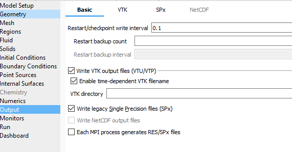
After you check the write VTK output files, you need to go to the VTK tab, add a new output using the +, select the data type (cells) and select what region, Next, select the data you actually want to save (volume fraction). To see the cells, use a region that has the entire domain and select at least one variable to write.
I am trying to upload a gif but apparently it is to big…
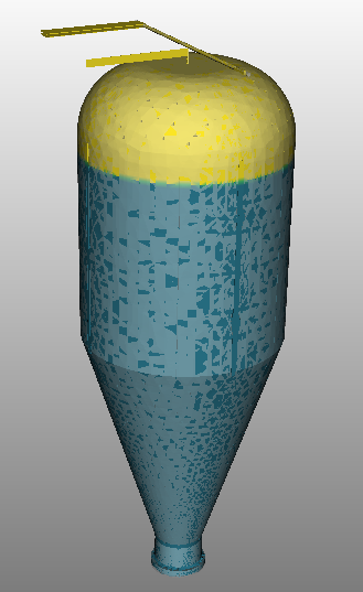
Now that I can see the vtk file at time=0, I can’t seem to get rid of cell leaking
. I’ve tried different stl resolution and grid resolution and placement. Here is the latest mfx file and stl base.mfx (20.8 KB)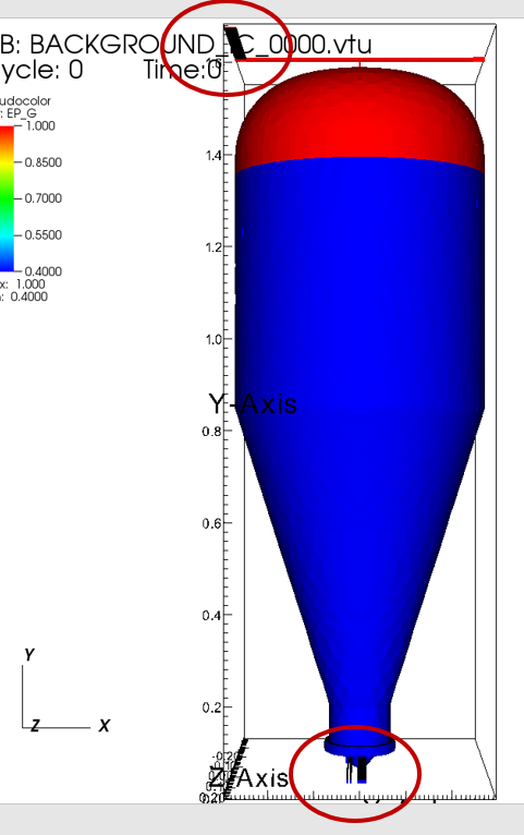
feed fuidizer with mods and no plenum_v2_v3.stl - Google Drive
Please try with the attached. base.mfx (23.4 KB)
The main issue with the geometry is the cup inlet region did not pick up all the cone facets. This can be verified by zooming in near the top of the cup inlet region and you will see a gap. You can alos look at geometry_0001.stl and geometry_0004.stl and see the gap. I moved the cup inlet region y extent to make sure there are no gap. I personally like to split my stl files, one for each BC, and use a selection method of “all” for each stl file.
I also put fewer control points. You will get better results at the top inlet and outlet if you extended the tube in the x-direction so it sticks out of the domain box.
There was some non-convergence due to bad initial condition. The initial void fraction in the bed (0.4) was lower than the max packing limit (0.42) so I arbitrarily adjusted some solids fractions to get above it.
Thanks for looking at this. Your revised base.mfx requires me to update to 19.1 but I have started another topic with problems I am having with that.