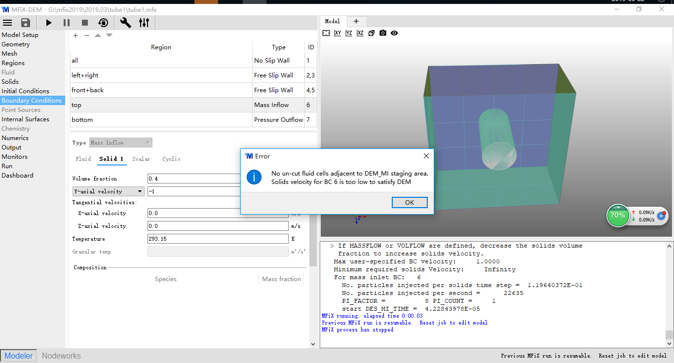
Hello everyone. How to solve the problem as shown in attachment?
ps: Pure granular flow fall down through a tube.
Is the tube open at the mass inlet plane? Make sure it is open, and try to extend it past the plane so it sticks out of the domain box
Sorry. There may be a mistake in my description. Properly speaking, it is a horizontal cylinder. The inlet plane is the top plane of the domain box, and the outlet plane is the bottom plane of the domain box. The particles fall down through the outside surface of the horizontal cylinder, and then discharge from the bottom plane of the domain box.
First look at the mesh to make sure you are modeling the correct side of the cylinder (outside in your case). Save cell data in a VTK file (output pane). Once you run the simulation, open a 3D View window to look at the mesh. I am suspecting it is inside out. Go to Mesh> Mesher and see if “External Flow” is checked. If it is checked and the mesh is inside out, this means the STL normals are pointing in the wrong direction. Uncheck “External Flow”, this will have the effect of flipping the STL normals.
Thank you. I unchecked External Flow. But there was also error as "No un-cut fluid cells adjacent to DEM_MI staging area ". I upload the files. I would appreciate you looking at it. Thank you very much.tube1.zip (11.6 KB)
I didn’t look at your case yet, but make sure the stl file extends outside the simulation domain.
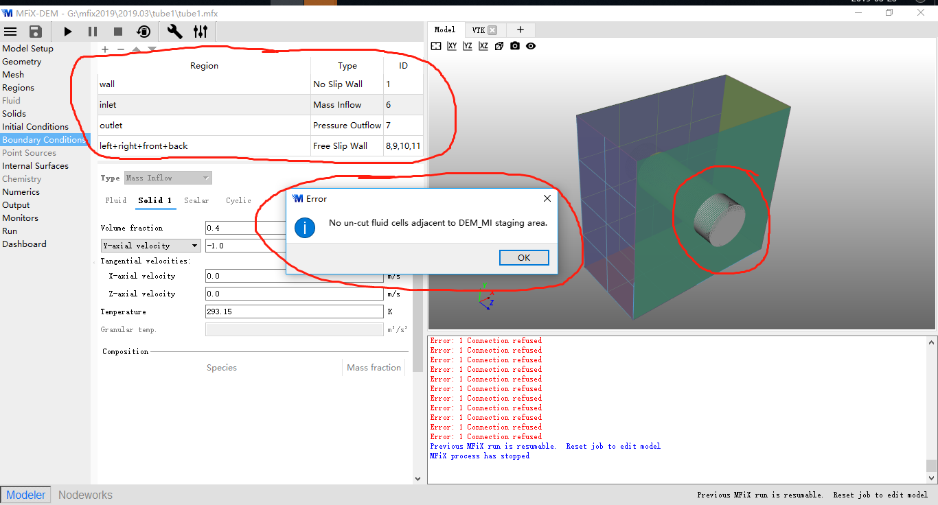
Thank you. The cylinder extends outside the simulation domain as shown(front side and back side). But there is also the same error. Is there a mistake in my Boundary conditions?
- The mesh is too coarse to resolve the cylinder. Increase the number of cells to 12x12x6
- Make sure “External Flow” is checked in Mesh>Mesher
- Remove left+right+front+back wall bcs. There is a bug in 18.1.5 that I believe has been fixed for the upcoming 19.1 release. There will be default walls BCs applied along those planes.
- When saving particle data in the vtk files, make sure to write particle diameter so the GUI can scale particles in the VTK window.
Thank you. I got it.
Excuse me, sir? You said the left+right+front+back planes are default walls Bcs. Are them adiabatic? Are they no slip walls, or free slip walls? In this case. the wall Bc of cylinder is no slip wall and the wall temperature is specified. Meanwhile, I want set the condition of left+right+front+back walls as free slip wall and they are adiabatic. How can I do that? Thank you.
You are not solving the energy equation so the temperature BC cannot be set. You are also not solving for the gas phase (granular flow), so no-slip vs free-slip is not relevant here. If you want to solve for the gas phase, and turn the energy equation on, wait a few days for the upcoming 19.1 release which will have the bug fix that prevents you from explicitly setting the wall bcs with this geometry.
Hi I am having a similar problem, if the mesh was inside out so I unspecified external flow (OUT_STL_VALUE = 1.0), does the stl still need to extend outside the mesh? Or would it be the opposite now?
It depends if/where the stl file intersects the bounding box, and if your stl file is closed or open. I like to keep my stl files open and have the inlets and outlets stick out of the bounding box. That way I define the inlets and outlets as regular BCs along planes.
Please note that as of version 19.1, there is a better way to flip normals and verify normals are pointing in the right direction. See https://mfix.netl.doe.gov/doc/mfix/19.1.4/reference/faq.html#how-to-verify-flip-stl-file-facet-normals . OUT_STL_VALUE is now a legacy keyword that I don’t recommend using unless you are loading an old input file.
I am having a similar problem, the issue is not with the geometry, I have different materials and different diameters, so I define several solids. rCould you please explain how to determine BC volume fraction with defined mass flow rate?