TFM simulation of iron ore bubbling fluidized bed: geometry, mesh resolution, and low solids suspension height

q24.mfx (10.5 KB)

Dear MFiX developers and users,

I am working on a cold bubbling fluidized bed simulation using MFiX-TFM. I would like to ask for advice about geometry generation, mesh resolution, and the problem that the simulated solids are not sufficiently suspended into the upper region of the bed.

My experimental system is a vertical cylindrical bubbling fluidized bed. The main parameters are:

  • Bed diameter: 0.06 m
  • Bed height: 1.35 m
  • Particle material: iron ore
  • Mean particle diameter: about 0.8 mm
  • Particle density: about 3822 kg/m3
  • Gas phase:ideal air
  • Model: MFiX-TFM
  • Drag model: mainly Gidaspow
  • Particle-particle restitution coefficient: 0.9
  • Experimental pressure taps are located at approximately 0.21 m, 0.46 m, 0.71 m, and 0.96 m.

In the experiment, the pressure at 0.45 m, 0.7 m, and even 0.95 m still has noticeable values, especially at higher gas flow rates. However, in my simulation, the pressure decreases too rapidly with height. The solids volume fraction above about 0.4 m becomes very low, and the particles mainly remain in the lower part of the bed. As a result, the simulated pressure at the upper pressure taps is much lower than the experimental pressure.

I would like to ask the following questions.

Question 1: Which method is recommended to generate the cylindrical geometry?

Question 2: What mesh size should be used relative to particle diameter?

My current mesh is approximately:

  • imax = 14
  • jmax = 320
  • kmax = 14

Would this be more suitable for this type of bed?

Also, should I refine the mesh in the y direction near the distributor / bed bottom region? The initial packed bed height is only about 0.145 m for one of my cases. The bottom region contains the inlet, distributor effect, and dense solids. I am wondering whether a non-uniform mesh with finer cells near the bottom and coarser cells in the upper freeboard is recommended.

For example, would it be better to use a finer grid in the lower region, such as from y = 0 to y = 0.3 m, and a coarser grid above 0.3 m? Or is a uniform y-direction mesh preferred for numerical stability in TFM?

Question 3: Why are the solids not suspended high enough, and why is the pressure above 0.4 m much lower than experiment?

This is my main problem.

In the experiment, the pressure along the bed height decreases gradually. Even at higher locations such as 0.46 m, 0.71 m, and 0.96 m, there is still a noticeable pressure signal. This suggests that the particles, bubbles, or dilute solids suspension can affect a relatively high region of the bed.

However, in my simulation:

  • Solids volume fraction decreases sharply above about 0.4 m.
  • Most of the particles remain in the lower part of the bed.
  • The pressure at 0.45 m and above is much lower than in the experiment.
  • The simulated bed expansion or solids suspension height is clearly lower than expected.

I am trying to understand what may cause this issue.

  1. Non-spherical iron ore particles
    The particles are iron ore, not ideal spherical glass beads or quartz sand. The particles are irregular and may have higher surface roughness. In the current TFM model, I use a spherical particle diameter of about 0.805 mm.

Thank you very much.
Question 1: Which method is recommended to generate the cylindrical geometry?
You should use the procedural method.

Question 2: What mesh size should be used relative to particle diameter?
Typically, it is recommended to have a grid size 10 times or less than the particle diameter. Yours appear to be about 5 times the particle diameter, so you should be good but you can do a grid sensitivity study to be sure. If you can afford it, use a uniform grid spacing. If you can’t you can use a finer mesh in the bed and a coarser mesh in the freeboard region, but make sure you have a smooth transition in between (no sudden jump in the grid spacing).

Question 3: Why are the solids not suspended high enough, and why is the pressure above 0.4 m much lower than experiment?
There are a number of things that could explain the difference:
a. Check your solid inventory to make sure it matches the experiment. Your pressure drop should be approximately the same as the weight of the bed. If you are loosing material at the top, you may need to increase the cylinder’s height or slowly ramp up the velocity to avoid the initial burst.
b. Check the Inlet BC velocity and pressure and outlet pressure.
c. You can try different drag laws to see if it makes a difference.
d. Refine the grid to see if it makes a difference.
e. The particle diameter is not representative of the experiment, either due to its shape and/or its particle size distribution.

Thank you very much for your suggestions.

I have recorded a short simulation video. In the simulation, the solids mainly remain below about 0.4 m, while in the experiment the solids are lifted much higher in the column.

For this case, my main settings are:
bianv.mfx (10.5 KB)

  • Model: MFiX-TFM
  • Bed diameter: 0.06 m
  • Bed height: 1.4 m
  • Particle material: iron ore
  • Experimental particle size range: 0.71–1.0 mm
  • In the simulation, I use one representative particle diameter, 0.805 mm, instead of the full particle size distribution
  • Particle density: about 3822 kg/m3
  • Drag model: Syamlal-O’Brien
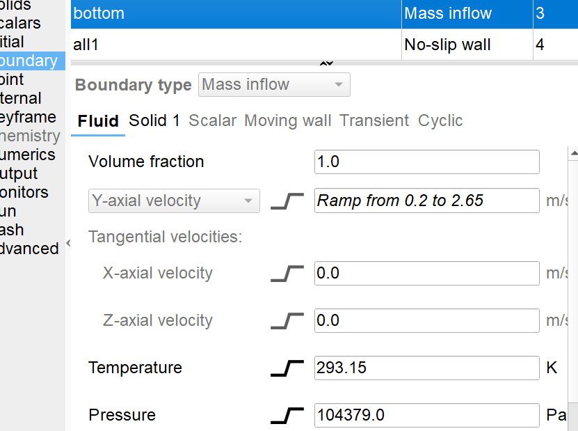
  • Bottom inlet: velocity inlet / mass inflow
  • Inlet velocity ramp: 0.2 m/s at 0 s to 2.65 m/s at 2 s

  • After 2 s, the inlet velocity remains 2.65 m/s
  • Inlet pressure: 104379 Pa
  • Top boundary: pressure outlet / outflow
  • Gas wall boundary: no-slip wall
  • Solids wall boundary: partial-slip / Johnson-Jackson type wall condition
  • Initial voidage: calculated from the experimental packed bed height and solids inventory

In the experiment, the pressure signal is still about 200 Pa at around 0.95 m. However, in the simulation, the solids volume fraction decreases sharply above about 0.4 m, and the pressure above 0.4 m is much lower than the experimental value.


My question is: why do the solids remain mainly below 0.4 m in the simulation, even with the inlet velocity ramp, while the experiment shows solids suspension and pressure fluctuations up to about 0.95 m?

Could this be mainly caused by the simplified inlet/distributor treatment, the drag law, particle non-sphericity, using one representative particle diameter instead of the full 0.71–1.0 mm size distribution, the gas no-slip wall condition, the solids wall boundary condition, or the initial solids inventory/packing?

Also, is it appropriate to specify both the inlet velocity ramp and an inlet pressure of 104379 Pa at the bottom boundary?

I attached the simulation video for reference. Thank you again for your help.

I attached the simulation video. Thank you again for your help.