Dear Expert,
how can I fix this error (DT < DT_MIN. Recovery not possible!). as I kept the mesh size of 3D cylinder (10,100,10) a total of 10000, where the aspect ratio is greater than 1 then the simulation runs while when I increased the size of the meshing (15,100,15) total 22000 simulations is not runining. Error comes (DT < DT_MIN. Recovery not possible!).
I also have one doubt about cylindrical geometry, I created through primitives cylinder and then applied static bed height in boundary condition it works, while when I createed a cylinder without using primitives static bed height it not coming (point coming in BC). is this actual cylinder or rectangular 3D?
Dear Jeff,
I tried to do it in all possible ways given in the manual but my simulation is not working and still getting the error: Error from time_step.f:196
DT < DT_MIN. Recovery not possible!
Fatal error reported on one or more processes. The .LOG file
may contain additional information about the failure.
In my case, all the residual getting values, and I also tried to reduce the time step size, changed the iteration of gas pressure 50, changed the ideal gas law in gas phase density, and changed the mesh tolerance, but the problem was not solved.
can you check what I am doing wrong, please find the bug report.
tfm3dwithenergy_2024-01-31T093957.760970.zip (28.0 MB)
- There is a conflict with your geometry and Boundary conditions. The cylinder is closed at the inlet and outlet, so you have both No slip wall and inlet/Outlet BCs. You should always inspect the mesh.
The left image shows that the BC is not well defined. Go in the geometry pane and increase the height of the cylinder to 1.1m. This will make the cyclinder stick out of the MFiX domain and you won’t have a conflict with the Inlet and Outlet BCs. The mesh should then look like the image on the right.
- Go to the Mesh>Mesher pane and change the normal distance tolerance to 0.05.
With the above 2 changes, it seems to run fine.
Dear Jeff,
Thank you for the help, I tried it but the problem is still the same. Two sides are not getting mesh.
Dear Jeff,
As mesh is created but only bottom side mesh is looking good, other side mesh is not looking right, can you send the modifed mesh mfix file here, it will be very helpful for me.
Please try the attached.
TFM3Dwithenergy.mfx (16.8 KB)
Dear Jeff,
Thank you for the help, I simulated the same case file but after 2.5 seconds the simulation stopped and the error was coming "DT < DT_MIN. Recovery is not possible! "
I tried to change the velocity at the numerical 1000 and pressure 100 iteration, but the problem is still coming. could you suggest to me what I am doing wrong?
But the debug file is too large, so I deleted the SP file and attached the debug file.
tfm3dwithenergy_2024-02-10T185304.314634.zip (54.5 MB)
Dear Expert,
How can I get the smooth contours plot of a 3D cylinder because it looks structured while I use a good mesh size (50000)?

Dear Jeff,
I would curiously like to know how I can achieve smooth 3D contours.
You can use a node representation instead of a cell representation:
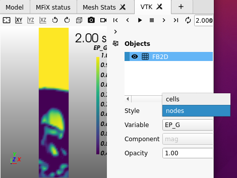
Thank you for your response:
I applied it but this is applicable in the 2d case not in the 3D case.
It works in 3D, but the cutcell topology makes it harder for the VTK filter to get smooth results.
Then what is the alternate option to get smooth contour plot.
If 3d geometry file export from other then it will give smooth contour plot.


