5.1. PIC01: Terminal velocity
5.1.1. Description
This case is similar to “DEM06: Single particle, terminal velocity”. A computational parcel containing physical particles is subjected to a uniform gas velocity. The statistical weight and initial gas volume fraction are adjusted such that all particles are accommodated in one parcel for the given grid resolution. The simulation results are compared with the analytical results obtained by solving the following system of Ordinary Differential Equations:
The initial and boundary conditions are given by,
where, \(y\) is the position of particle center measured from the bottom wall, \(v_{p}\) and \(v_{g}\) are the particle and gas velocities, \(\rho_{p}\) and \(\rho_{g}\) are particle and gas densities, \(d_{p}\) is the particle diameter, \(h_{0}\) is the initial height of the particle, \(g\) is the acceleration due to gravity, and \(C_{d}\) is the drag coefficient. In this case, \(C_{d}=1\) is used for simplicity. The effect of the parcel on the gas phase is neglected since particle concentration is extremely dilute. Hence, the momentum equations for the gas-phase are not solved.
5.1.2. Setup
Computational/Physical model |
|||
|---|---|---|---|
3D, Transient |
|||
Multiphase |
|||
Gravity |
|||
Thermal energy equation is not solved |
|||
Turbulence equations are not solved (Laminar) |
|||
Uniform mesh |
|||
First order upqind discritization scheme |
|||
Geometry |
|||
Coordinate system |
Cartesian |
Grid partitions |
|
x-length |
0.01 |
(m) |
5 |
y-length |
0.30 |
(m) |
60 |
z-length |
0.01 |
(m) |
5 |
Material |
|||
Gas density, \(\rho_{g}\) |
1.2 |
(kg·m-3) |
|
Gas viscosity, \(\mu_{g}\) |
1.8E-05 |
(Pa·s) |
|
Solids Type |
PIC |
||
Diameter, \(d_{p}\) |
0.1 |
(m) |
|
Density, \(\rho_{s}\) |
2000 |
(kg·m-3) |
|
Solids Properties (PIC) |
|||
Pressure linear scale factor, \(P_{s}\) |
100.0 |
(Pa) |
|
Exponential scale factor, \(\gamma\) |
3.0 |
(-) |
|
Statistical weight |
100 |
(-) |
|
Initial Conditions |
|||
x-velocity, \(u_{g}\) |
0.0 |
(m·s-1) |
|
y-velocity, \(v_{g}\) |
0.4 |
(m·s-1) |
|
z-velocity, \(w_{g}\) |
0.0 |
(m·s-1) |
|
Solids concentration, \(\epsilon_{s}\) |
0.0001 |
(-) |
|
Gas volume fraction at packing, \(\epsilon_{g}^{*}\) |
0.4 |
(-) |
|
Pressure, \(P_{g}\) |
101,325 |
(Pa) |
|
Boundary Conditions |
|||
South |
0.4 |
(m·s-1) |
Mass inflow |
North |
101,325 |
(Pa) |
Pressure outflow |
West, east, top and bottom |
Free-Slip wall |
5.1.3. Results
As the parcel falls, its velocity increases initially, and reaches its terminal velocity when the gravitational force is balanced by the drag force. The numerical solution to the system of equations is obtained using \(4^{th}\) order Runge-Kutta method. The values are compared with the MFiX-PIC simulations as shown in Fig. 5.1. The velocity and position are accurately predicted by MFiX-PIC as was the case with MFiX-DEM.
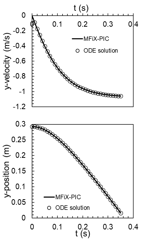
Fig. 5.1 Predictions using MFiX-PIC: velocity (top) and position (bottom).