Defining the domain
All simulations, whether using an embedded boundary (EB) or not, are specified on a simple cuboid domain. The
low and high corners of the cuboid are defined by the prob_lo and prob_hi inputs.
The following inputs are defined using the prefix geometry:
Description |
Type |
Default |
|
|---|---|---|---|
coord_sys |
Coordinate system used in simulation. Only Cartesian coordinates
( |
Int |
0 |
prob_lo |
Low corner of physical domain (physical not index space) |
Reals<3> |
None |
prob_hi |
High corner of physical domain (physical not index space) |
Reals<3> |
None |
Attention
MFIX-Exa geometry restrictions:
There is no support for 1D or 2D simulation domains.
Cartesian is the only supported coordinate system.
Mesh
The following inputs are defined using the prefix amr:
Description |
Type |
Default |
|
|---|---|---|---|
n_cell |
Number of cells at level 0 in each coordinate direction. Must be
divisible by |
Ints<3> |
None |
The base mesh spacing is computed for each direction by dividing the domain length by the number of cells. The mesh spacing is required to be the same in all directions:
The inputs for defining the mesh for a single-level simulation are demonstrated in the following example and illustrated in Fig. 1. In this example, the domain is a \(4 \times 1 \times 1\) cuboid, and there are \(32 \times 8 \times 8\) cells in the X, Y, and Z directions, respectively. The result is a uniform mesh spacing of \(0.125\) m in all three directions.
# Define periodicity and domain extents
# -------------------------------------------------------------
geometry.coord_sys   =  0           # Cartesian coordinates
geometry.is_periodic =  0   0   0   # periodicity for each direction
geometry.prob_lo     =  0.  0.  0.  # lo corner of physical domain.
geometry.prob_hi     =  4.  1.  1.  # hi corner of physical domain

# Define the maximum level of refinement and number of cells
# -------------------------------------------------------------
amr.n_cell = 32  8  8
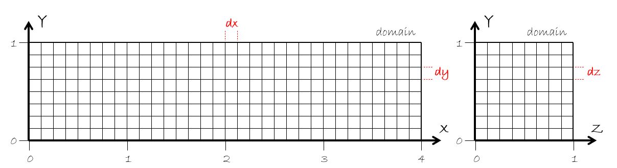
Fig. 1 Example of a single-level mesh.
Warning
MFIX-Exa simulations with a non-uniform mesh will not run.
Grid settings
The following inputs are defined using the prefix amr:
Description |
Type |
Default |
|
|---|---|---|---|
max_grid_size_x |
Maximum number of cells in each grid in X. Can be specified per-level. |
Ints |
32 |
max_grid_size_y |
Maximum number of cells in each grid in Y. Can be specified per-level. |
Ints |
32 |
max_grid_size_z |
Maximum number of cells in each grid in Z. Can be specified per-level. |
Ints |
32 |
blocking_factor_x |
Each grid in X must be divisible by |
Ints |
8 |
blocking_factor_y |
Each grid in Y must be divisible by |
Ints |
8 |
blocking_factor_z |
Each grid in Z must be divisible by |
Ints |
8 |
Note, the default for max_grid_size is 64 for GPU runs.
The domain is decomposed into grids by dividing the number of cells by the max grid size
for each direction (e.g., n_cells[0]/max_grid_size_x). The blocking factor ensures that
the grids will be sufficiently coarsenable for good multigrid performance; therefore, the
max_grid_size must be divisible by the corresponding blocking_factor.
Note
The AMReX documentation contains a significant amount of information on grid creation and load balancing. Users are strongly encouraged to read the relevant sections.
Periodic domains
The following inputs are defined using the prefix geometry:
Description |
Type |
Default |
|
|---|---|---|---|
is_periodic |
1 for true, 0 for false (one value for each coordinate direction) |
Ints<3> |
0 0 0 |
Pressure drop
The following inputs are defined using the prefix mfix:
Description |
Type |
Default |
|
|---|---|---|---|
delp_dir |
Direction for specified pressure drop. The domain must be periodic in the the specified direction.
|
Int |
None |
delp |
Pressure drop (Pa) |
Real |
0 |
Reference frame
MFIX‑Exa supports simulations in either an inertial (laboratory) reference frame or a uniformly rotating reference frame. The choice of reference frame affects how momentum equations are solved and whether additional pseudo‑forces (Coriolis and centrifugal) are included in the fluid and solids momentum balances.
The following inputs are defined using the prefix mfix:
Description |
Type |
Default |
|
|---|---|---|---|
reference_frame |
Specifies the reference frame in which the governing equations are evaluated.
|
String |
inertial |
The following inputs are defined using the prefix reference_frame:
Description |
Type |
Default |
|
|---|---|---|---|
axis |
The direction of the rotation axis in physical space. |
Reals<3> |
None |
axis_point |
The location through which the rotation axis passes. |
Reals<3> |
None |
angular_speed |
Scalar angular speed of the rotating frame, in radians per second. |
Real |
None |