Specifying a geometry
The following inputs are defined using the prefix mfix:
Description |
Type |
Default |
|
|---|---|---|---|
geometry |
Simulation geometry type. Options (case-insensitive):
|
String |
Most simulations require a user to specify some kind of geometry. For example, the geometry could be a basic cylinder used to model flow inside a pipe, or it may be an irregularly shaped solid to study external flow around a bluff body, or the geometry may be the proposed design of a complex, multi-stage chemical reactor undergoing performance assessment. In the following sections, several options for specifying a geometry are described.
Caution
Any domain extent that is not periodic or defined as a Dirichlet or Neumann boundary condition must be fully covered. To state this another way, if a domain extent is not periodic or an inflow or outflow boundary condition, then it should be excluded from (outside of) the domain by the embedded boundary geometry.
Predefined geometries
The mfix.geometry input is used to choose one of the basic predefined geometries, or to
select the option to use a user-defined geometry constructed from native AMReX implicit functions.
box geometry
The following inputs are defined using the prefix box:
Description |
Type |
Default |
|
|---|---|---|---|
Lo |
Low corner of the embedded boundary box |
Reals<3> |
|
Hi |
High corner of the embedded boundary box |
Reals<3> |
|
internal_flow |
Indicates that flow is inside the box. |
Bool |
true |
offset |
Shift low side box walls by |
Real |
1.0e-15 |
box limitations
The predefined EB box geometry has several limitations:
The sides of the box should not coincide with the domain extents.
A
boxis aligned with the coordinate axes and cannot be rotated in any direction.There can only be one
box. Multiple boxes cannot be defined and combined.
box example
The domain is a \(2 \times 2 \times 8\) cuboid where X and Y span \([-1,1]\),
and Z spans \([0,8]\). A \(10\) meter long embedded boundary box with a
\(1 \times 1\) cross-section runs lengthwise through the domain, centered about the
Z axis. The EB is shifted down the Z axis so that there is a \(-1\) meter
overhang on the low and high Z domain faces.
box geometry example. This is not a complete input file.¶# Define periodicity and domain extents
# -------------------------------------------------------------
geometry.coord_sys = 0 # Cartesian coordinates
geometry.is_periodic = 0 0 1 # periodicity for each direction
geometry.prob_lo = -1. -1. 0 # lo corner of physical domain.
geometry.prob_hi = 1. 1. 8. # hi corner of physical domain
# Select box geometry and specify settings
# -------------------------------------------------------------
mfix.geometry = box
box.Lo = -0.5 -0.5 -1.0
box.Hi = 0.5 0.5 9.0
box.offset = 0.
box.internal_flow = true
Fig. 2 illustrates the (grey) domain and (blue) embedded
boundary box geometry. The left image is a 3D rendering of the setup, and
the center and right images are 2D slices along the XZ and XY planes, respectively.
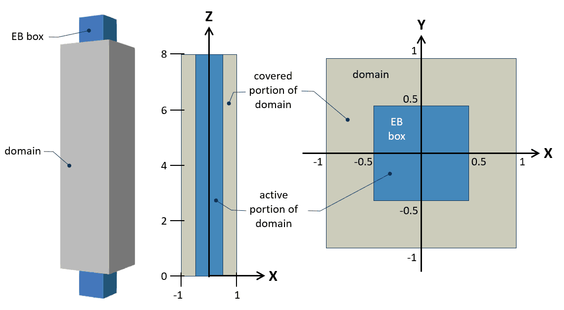
Fig. 2 Example of predefined embedded boundary box geometry with the EB colored blue and the domain colored grey.
Left: the domain and EB are rendered in 3D.
Center: a 2D slice showing the XZ plane.
Right: a 2D slice showing the XY plane.
This is an internal flow setup, therefore the sections of the domain that do not intersect
the EB box are covered and thereby excluded from run-time calculations.
No boundary conditions are needed for the low and high domain faces in X and Y because they are fully covered.
The low and high Z domain faces remain uncovered, however no boundary conditions are needed because the domain is periodic in Z (see the inputs snippet for this example ).
cylinder geometry
The following inputs are defined using the prefix cylinder:
Description |
Type |
Default |
|
|---|---|---|---|
radius |
Cylinder radius. |
Real |
|
height |
Height (length) of cylinder. If the height is not defined (-1), then the cylinder is made infinitely long to overhang the domain extents. |
Real |
-1 |
direction |
Axis the cylinder runs along. Options:
|
Int |
0 |
center |
Center of cylinder. For a cylinder with an undefined |
Reals<3> |
|
rotation |
Rotation angle of cylinder, in degrees.
|
Real |
|
rotation_axis |
Axis to rotate the cylinder about. Options:
|
Int |
0 |
internal_flow |
Indicates that flow is inside the box. |
Bool |
true |
The inputs for the predefined cylinder embedded boundary geometry are illustrated in Fig. 3.
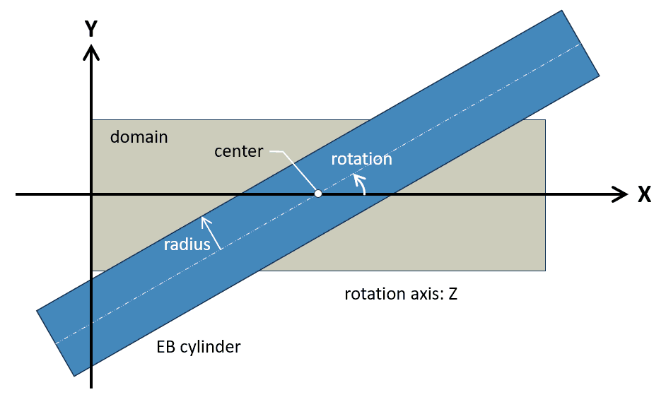
Fig. 3 Illustration of predefined embedded boundary cylinder geometry inputs where the cylinder geometry is
blue and the domain is grey.
cylinder limitations
The predefined EB cylinder geometry has several limitations:
The ends of the
cylindershould not coincide with the domain extents. Thecylindershould be shorter than the domain, or sufficiently long that it overhangs the ends of the domain.Rotations are about a single axis.
There can only be one
cylinder. Multiple cylinders cannot be defined and combined.
cylinder example
The domain is a \(4 \times 1 \times 1\) cuboid where Y and Z span \([0,1]\),
and X spans \([0,4]\). An embedded boundary cylinder with \(0.45\) radius
runs lengthwise through the domain, offset by \([0.5]\) in the Y and Z, respectively.
The cylinder is not assigned a length, therefore it runs past the low and high X domain faces.
cylinder geometry example. This is not a complete input file.¶# Define periodicity and domain extents
# -------------------------------------------------------------
geometry.coord_sys = 0 # Cartesian coordinates
geometry.is_periodic = 0 0 0 # periodicity for each direction
geometry.prob_lo = 0. 0. 0. # lo corner of physical domain.
geometry.prob_hi = 4. 1. 1. # hi corner of physical domain
# Select cylinder geometry and specify settings
# -------------------------------------------------------------
mfix.geometry = cylinder
cylinder.internal_flow = true
cylinder.radius = 0.45
cylinder.direction = 0
cylinder.center = 0.0 0.5 0.5
Fig. 4 illustrates the (grey) domain and (blue) embedded
boundary cylinder geometry. The left image is a 3D rendering of the setup, and
the center and right images are 2D slices along the XZ and YZ planes, respectively.
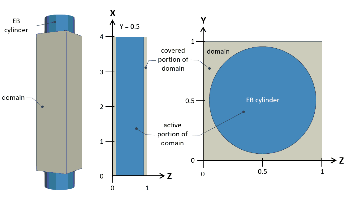
Fig. 4 Example of predefined embedded boundary cylinder geometry with the EB colored blue and the domain colored grey.
Left: the domain and EB are rendered in 3D.
Center: a 2D slice showing the XZ plane.
Right: a 2D slice showing the YZ plane.
This is an internal flow setup, therefore the sections of the domain that do not intersect
the EB cylinder are covered and thereby excluded from calculations.
No boundary conditions are needed for the low and high domain faces in Y and Z because they are fully covered.
The low and high X domain faces remain uncovered, therefore boundary conditions are needed to fully specify the problem. Example boundary conditions include a mass inflow on the low X face and a pressure outflow on the X high face.
sphere geometry
The following inputs are defined using the prefix sphere:
Description |
Type |
Default |
|
|---|---|---|---|
radius |
Sphere radius. |
Real |
None |
center |
Center of sphere. |
Reals<3> |
|
internal_flow |
Indicates that flow is inside the sphere. |
Bool |
false |
generic geometry
The generic geometry option is used to select the user-programed embedded boundary geometry.
A custom embedded boundary geometry is programmed by the user in
src/eb/mfixeb_generic.cppusingAMReXnative implicit functions and operations.An executable containing the geometry modifications is compiled.
The geometry is accessed using the
genericinput.
Note
A full description of this feature is beyond the scope of this section. A future update to the documentation may include a tutorial to better demonstrate this capability.
CSG (Constructive solid geometry)
A constructive solid geometry can be created using OpenSCAD.
This option requires that the executable be built with CSG support. See the build documentation for for details.
The following inputs are defined using the prefix csg:
Description |
Type |
Default |
|
|---|---|---|---|
geometry_filename |
The CSG file that defines the EB geometry. |
String |
‘’ |
scaling_factor |
Scale the geometry. |
Reals<3> |
|
translation |
Translate the geometry. |
Reals<3> |
|
internal_flow |
Indicates that flow is inside the the CSG geometry. |
Bool |
true |
Note
A full description of this feature is beyond the scope of this section. A future update to the documentation may include a tutorial to better demonstrate this feature.
STL (Stereolithography file)
An STL geometry can be created using numerous CAD programs.
The following inputs are defined using the prefix stl:
Description |
Type |
Default |
|
|---|---|---|---|
geometry_filename |
The STL file that defines the EB geometry. |
String |
‘’ |
scaling_factor |
Scale the geometry. |
Real |
|
translation |
Translate the geometry. |
Reals<3> |
|
internal_flow |
Indicates that flow is inside the STL geometry. |
Bool |
true |
use_bvh |
Use bounding volume optimization. |
Bool |
true |
Note
A full description of this feature is beyond the scope of this section. A future update to the documentation may include a tutorial to better demonstrate this feature.
Levelset refinement
For particle-wall interactions, the geometry is represented using a levelset function, and the grid storing this levelset can be refined to capture geometric details more accurately. This refinement affects only particle-wall interactions and does not alter the geometry representation used for solving the fluid equations.
The following inputs are defined using the prefix mfix:
Description |
Type |
Default |
|
|---|---|---|---|
levelset_refinement |
Refinement factor of levelset resolution relative to level 0 resolution |
Int |
1 |
Embedded boundary
The following inputs are defined using the prefix eb2:
Key |
Description |
Type |
Default |
|---|---|---|---|
cover_multiple_cuts |
If |
Bool |
false |
maxiter |
Fixing small and multi-cut cells is an iterative process. This parameter specifies the maximum number of iterations for the fix-up process. |
Int |
32 |
small_volfrac |
Specifies the threshold for small cells that will be converted to covered cells, as a fraction of the total cell volume. |
Real |
1e-14 |