2.9. MMS05: Free-slip wall BC, single-phase, 3D, curl-based functions¶
2.9.1. Description¶
The free-slip wall boundary condition in MFIX is verified using the techniques described in [5] where the manufactured solution is selected such that it satisfies both the divergence-free constraint and the free-slip wall boundary condition. Specifically, the normal velocity component is zero at the (stationary) free-slip wall while the tangential velocity component is imposed by specifying appropriate values in the ghost cells adjacent to the wall. This results in a zero gradient condition normal to the free-slip wall for the tangential velocity components only. The manufactured solution for the velocity field used for the verification of a free-slip wall is given as [6]:
where, \(\overrightarrow{V}\) is the velocity field vector, \({\overrightarrow{V}}_{0} = \left\{ 0,v_{0},w_{0} \right\}^{T}\) consists of non-zero scalar constants for \(v_{0}\) and \(w_{0}\), \(S\) is the mathematical equation of the boundary tested (i.e., \(S \equiv x = 0\)), and \(\overrightarrow{H}\) is a general vector field consisting of sinusoidal expressions. The pressure manufactured solution is selected as in Eq.6.1 since there are no constraints on pressure with this boundary condition.
2.9.2. Setup¶
This case is setup for single-phase flows on a domain with unit dimensions; the boundary tested is the West boundary (i.e., \(x = 0\)).
Computational/Physical model |
||
|---|---|---|
3D, Steady-state, incompressible |
||
Single-phase (no solids) |
||
No gravity |
||
Thermal energy equations are not solved |
||
Turbulence equations are not solved (Laminar) |
||
Non-uniform mesh |
||
Central scheme |
||
Geometry |
||
Coordinate system |
Cartesian |
|
Domain length, \(L\) (x) |
1.0 |
(m) |
Domain height, \(H\) (y) |
1.0 |
(m) |
Domain width, \(W\) (z) |
1.0 |
(m) |
Material † |
||
Fluid density, \(\rho_{g}\) |
1.0 |
(kg·m-3) |
Fluid viscosity, \(\mu_{g}\) |
1.0 |
(Pa·s) |
Initial Conditions |
||
Pressure (gauge), \(P_{g}\) |
MMS |
(Pa) |
Fluid x-velocity, \(u_{g}\) |
5.0 |
(m·s-1) |
Fluid y-velocity, \(v_{g}\) |
5.0 |
(m·s-1) |
Fluid z-velocity, \(w_{g}\) |
5.0 |
(m·s-1) |
Boundary Conditions ‡ |
||
West boundary |
Free-slip wall |
|
All other boundaries |
Mass inflow |
† Material properties selected to ensure comparable contribution from convection and diffusion terms.
‡ The manufactured solution is imposed on all boundaries (i.e., Dirichlet specification).
2.9.3. Results¶
Numerical solutions were obtained using the Central discretization scheme for 8x8, 16x16, 32x32, 64x64, and 128x128 grid meshes. Iterative convergence could not be achieved for this case when pressure was solved. Hence, the pressure variable (\(P_{g}\)) was fixed by specifying pressure using the manufactured solution in the initial conditions routine and discarding the pressure solution in the main solver routine. The observed order of accuracy matches the formal order as shown in Fig. 2.17 for the velocity variables.
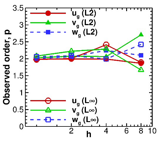
Fig. 2.17 Observed orders of accuracy for free-slip wall verification (3D, single-phase flows) using \(\mathbf{L}_{\mathbf{2}}\) and \(\mathbf{L}_{\mathbf{\infty}}\) norms of the discretization error.¶